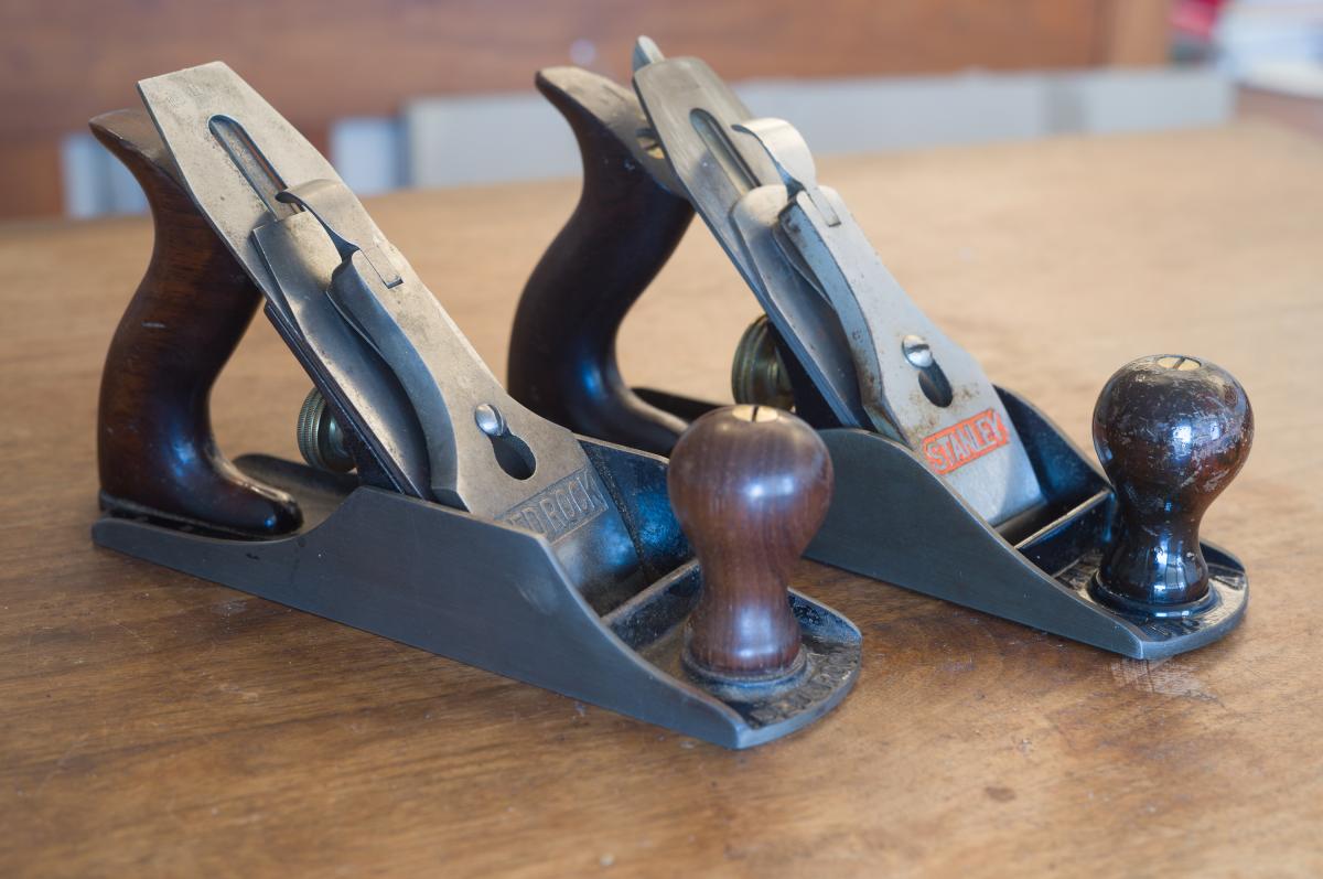
L-R Late model Bedrock 604, Stanley #4
There is a lot of information out there about Stanley planes - even the minutia associated with small changes in their design. But I am more interested in the major changes that affect performance.
The basic Stanley mechanism that all know and love, was invented by Leonard Bailey, marketed by the Stanley Rule and Level Company and introduced to the market in 1867. It was a masterpiece of manufacturing engineering. It took advantage of the introduction of precision machine tools, which at the time were still uncommon, to make a metal, adjustable bench plane that could be made by machine, bolted together and work really, really well.
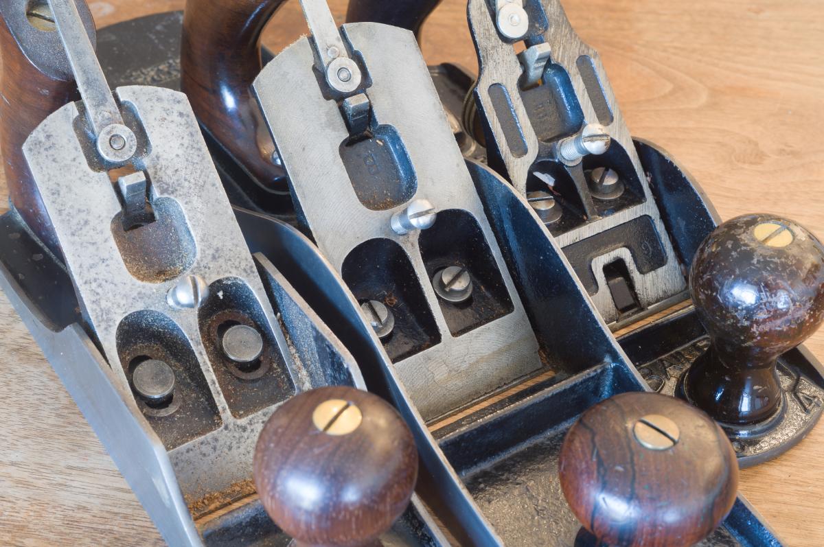
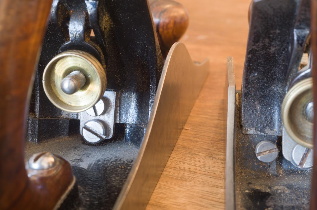
By 1898, the original patents had all expired, and maybe for that reason - or more likely the need for something to set their planes apart from copycats - Stanley introduced a new line of premium planes that they called their Bedrock planes. To reflect the new line, a new numbering sequence was used, Over time Stanley made Bedrock models going from 602 through 608, reflecting the original bench plane numbers of #2-#8. There is no Bedrock 601. L-R Post 1911 604, 1898 605 1/2, late #4 The regular frog on a Stanley bench plane is machined only on four small points of contact, of which only two are bolted down The 1898 Bedrock frog is bolted down. The only change is the wide machined mating surfaces
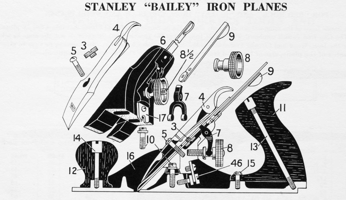
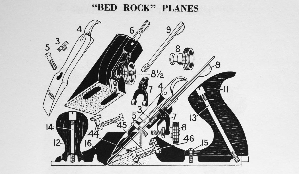
The new line tried to address two problems with the original planes. Admittedly, these were high class problems. The basic Stanley plane consists of two castings that are bolted together. The plane bottom (part 16 in the diagrams below) has two machined posts and a small machined area behind the mouth of the plane. The frog (part 6) has four small machined which correspond to the machined areas on the plane bottom and the two pieces are bolted together with two bolts. In 1867, this was high tech. In 1898, not so much. The problem is with just a small area of actual contact, really just the two bolt posts, any resistance to the blade caused by spots of hard wood or anything could cause the entire frog to vibrate slightly, resulting in chatter and other bad things. The only real way of stopping this is have a very, very sharp iron.
The second problem is that, should you decide to adjust the frog to move it in or out, opening or closing the mouth of a plane, you would have to do it by removing the iron and loosening the two frog clamping screws (part 10 below). There's really no positional reference once the frog is loosened, so it's very hard to adjust the frog and then tighten it square to the mouth, so that everything works properly once reassembled. Since 1907, Stanley planes have had a frog adjustment screw (part 46 in the diagrams below) that makes this considerably easier, but there's still a lot of play in the two castings, and in 1898 the base Stanley planes bench planes did not have this feature.
In 1898, the Bedrock line was introduced with three major new features. The first and most important feature was the replacement of the two-points-of- contact between frog and base with a large, flat, machined bed, so when you clamped the frog down, there was a tremendous amount of contact (thereby reducing chatter) and a smooth channel so the frog could also move back and forth and stay parallel to the mouth of the plane. A frog adjustment screw (part 46) was added so you could precisely move the front back and forth (even though you still had to take the blade off to move the frog). Frog adjustment screw on early c. 1898 Bedrock 605 1/2
The frog adjustment screw was a big improvement, and in 1907 it was added to the basic bench plane lineup. At the same time Stanley beefed up the regular frog casting. With this improvement, there still was only two points of contact, but the frog was slightly better aligned. These additions made the added features of the Bedrock a little bit less important. In 1911, Stanley added something brilliant to the Bedrock line. The two clamping screws on the frog were replaced with pins that slid into holes in the sole casting. On the side of each pin is a little v notch (part 44). In the sole casting two screws (part 45) were added running parallel to the sole so when tightened the screws engaged the notch in the pins, pulling them tightly down. Now, without removing the plane iron, all you had to do to adjust the frog position was to loosen the two screws on either side of the frog adjustment screw, and - by turning the frog adjustment screw - move the frog precisely to where you wanted it. Finally you could see what you were doing. To further denote that these planes were special: the round sides of the typical bench plane line were replaced on the Bedrock line with square sides.
The line continued being made by Stanley up until 1943. When Clifton and Lie-Nielsen revived making bench planes, they copied the Bedrock mechanism.
The early Bedrocks were made from 1898 to 1911. They are readily found in the wild, but they're not particularly desirable. The square sided ones fetch a premium.
Whether or not you think a Bedrock plane performs better than a stock Stanley, you must admit that the mechanism itself, which uses pressure on pins to clamp the frog in place, is an ingenious piece of mechanical engineering.
Does a Bedrock plane perform better than a stock Stanley? In my opinion the answer is yes, but there are far more important criteria for performance then having a Bedrock design. Another thing to remember is that your Bedrock plane is at least 80 years old and can have all sorts of issues depending on if they were used or abused. If you are interested in Stanley tools, having a copy of the 1914 Stanley Tools Catalogue No. 34 is extremely handy.
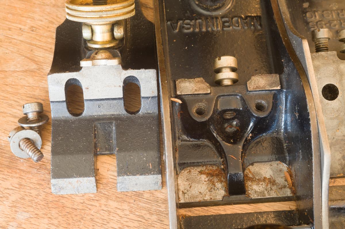
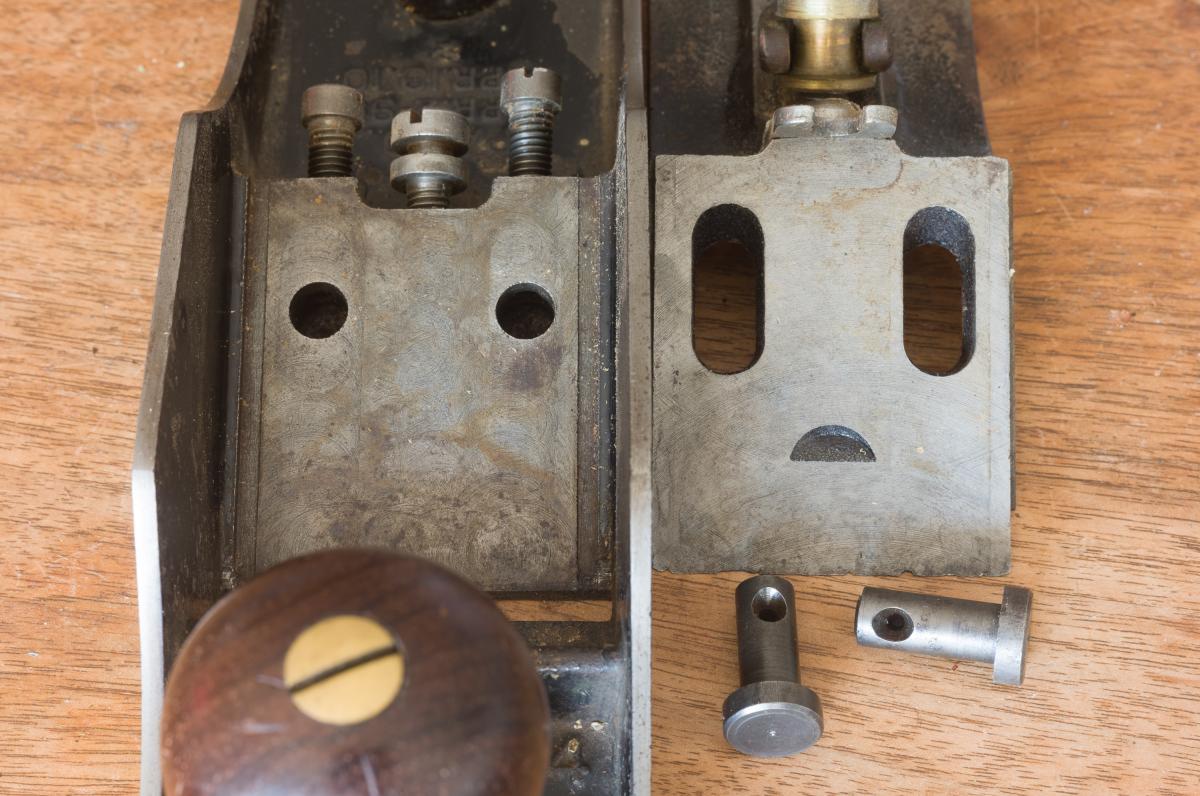
When the plane is disassembled the frog clamping pins and the wide bearing surfaces for solidly mounting the frog can be clearly seen
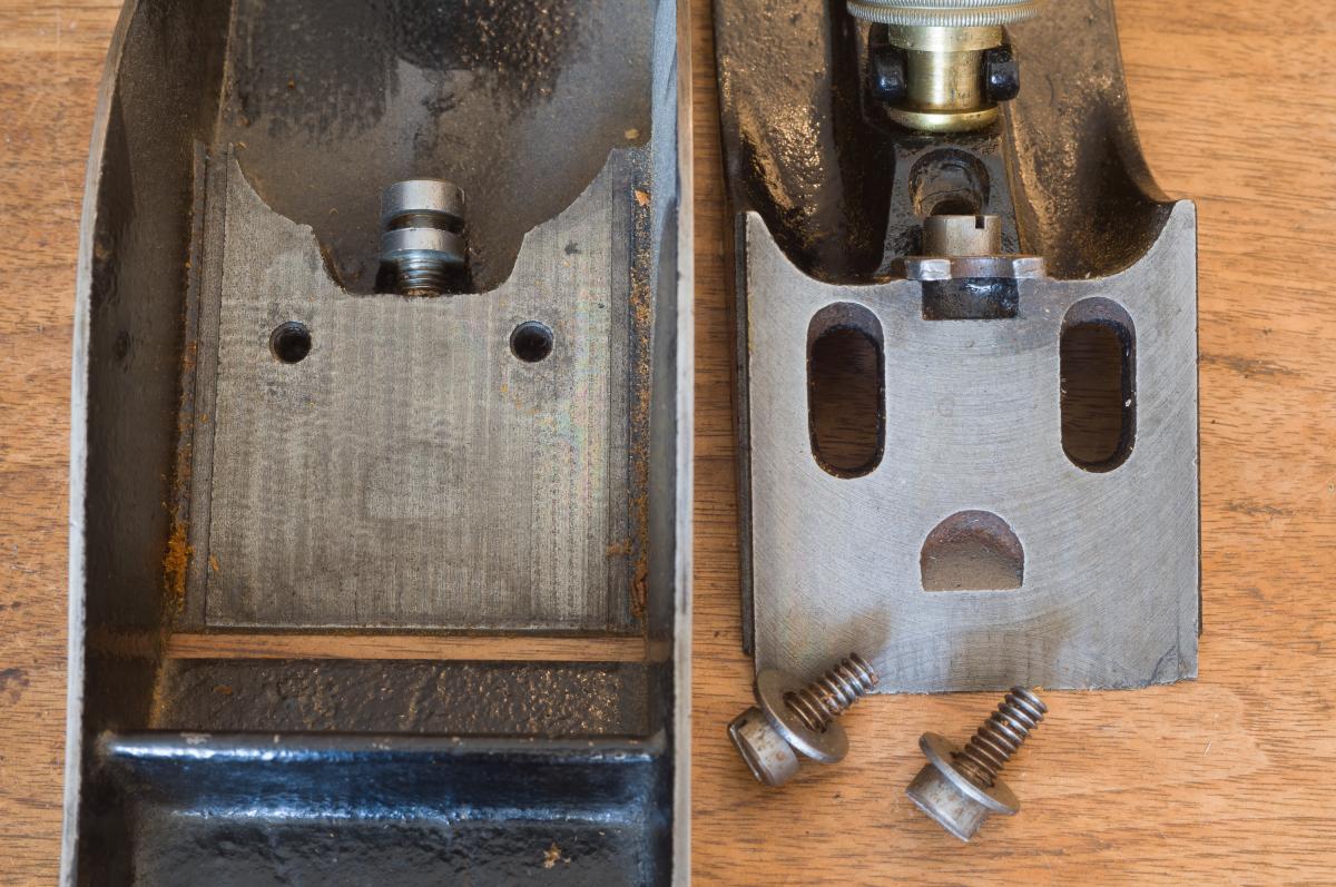
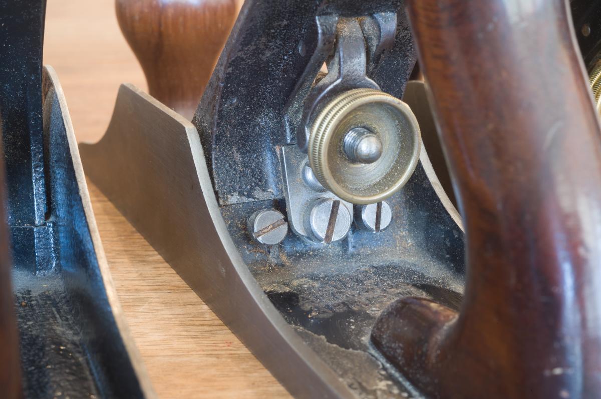
Back of a Bedrock 604 showing frog adjustment screw and frog clamping screws
Diagram of Stanley bench plane parts
Diagram of Bedrock bench plane parts
Join the conversation
08/17/2022 CT Engineer
Finally I understand why the square side Bedrock planes are so desirable. I used to think it was collectors driving up the price of rarer, premium planes. You have really (finally) driven home the origin of the name "Bedrock". Sadly, that realization likely comes after the opportunity to affordably own one has passed.
08/17/2022 Michael O’Brien
Very good article Joel, thank you. One point to mention is that when adjusting the frog of a Bedrock plane, to close or open the throat, it will also change the position of the plane blade’s edge relative to the sole. Example, the the blade’s setting prior to frog adjustment will move downward if you close the throat. This is not the case in a standard Bailey frog as the plane’s blade will remain exactly where it was prior to the frog’s adjustment. The reason is that the standard Bailey frog’s points of contact are parallel to the sole and move coplanar during frog adjustment. The Bedrock frog is on a sliding incline ramp and is not coplanar. So you have to readjust the blade setting after frog adjustment on a Bedrock to have it be at the same depth as it was prior to the frog’s adjustment. A Good thing to remember. Cheers, Michael
08/17/2022 Eric Z
I have never used or had a Bedrock. I could not see any significant feature superior to the standard Bailey of similar time frame that can justify the cost Bedrocks command today. I do see the handiness of the "pin" retained frog. Thank you for pointing that out...that I was unaware of.
I have to confess I come from a machining background...46 years in mold making. I tend to disagree with your assessment that:
"The regular frog on a Stanley bench plane is machined only on four small points of contact, of which only two are bolted down". This does actually happen...but not to all of the standard line. I have a #7 that this was really bad. The frog vibrated badly in anything other than the softest straightest pine. I was frustrated and reckoned that a Bedrock must be better but I just didn't want to spend the money they command. I set about to rework this #7 and correct the issues. The issue was exactly as you state: the frog retaining screws only bore against the two upper pads of the body. Now that looked incredibly silly to me and have a hard time understanding why it would be DESIGNED that way. Perhaps, it wasn't designed that way rather, just a bit beyond the machining and or casting techniques/tools of the day. Having experience with setting up milling machines this appears to be a simple toe clamp arrangement
https://www.cartertools.com/lms15.jpg
The stud being the frog retaining screw(s), the toe clamp being the frog whose heel is supported by packing (the step block which represents the plane body upper pads) and the toe bearing against the work piece representing the potential area where frog bears against the mouth of the plane body. Noting your diagram of the Stanley plane I sincerely believe that the frog was meant to be contacting all four points simultaneously. I have had some that do...and that #7 that didn't...not even close. Clearly, this was a bit of a challenge for them to machine in the era we are speaking of: Machining two levels in the confined area of the body to correct height AND then doing the same to oddly shaped and consequently challenging to fixture frog AND then do this interchangeably between a crate full of frogs and bodies during assembly.
Remember, this was the era of interchangeability of parts was still an ongoing challenge. Samuel Colt whom stated his guns were made from fully interchangeable parts was forced to redact that claim and later stated nearly interchangeable. No carbide cutting tools and barely into the era of High Speed Steel cutting tools, especially end mills for machining the body. That is a steep hill.
Clearly, the Bedrock with a single plane machined on an angle to the body sole and a corresponding single plane machined on the frog was a much simpler approach albeit with more material to remove.
Atop that machining issue with the standard Bailey, I have seen the castings of the body have quite a varying amount of upper pad surface. The issue seems to arise with pattern shifts and variances: The toe end of that upper pad tends to get too far forward toward the screws. This can happen from too much material being milled off and thus being farther down on the draft of the pattern's vertical wall and/or the pattern simply shifting.
Having access to and being quite capable with a milling machine and surface grinders, I set about to "correct" my planes that actually needed it. I milled the toe end of that upper pad back perhaps 1/8" away from the mouth. The result is, as the screw bears on frog, the frog will contact upper pad and continued tightening forces the frog to fulcrum about the upper pad (as there is no longer material under screw just like a toe clamp)and the frog is forced to contact body at the mouth. This simple modification (correction?) turns a practically unusable wretched tool into a simple wonderful and rock solid plane. Vibration be gone. I actually feel adjusting the frog in a plane parallel to the sole (standard Bailey design) is a more logical method that on a dissimilar angle (like the Bedrock).
That blather all said, I repeat I have never had a Bedrock or even handled one. But after modifying, along with precision grinding the entire body sole and sides, flat and square to .001" TIR, I feel a Bedrock can do nothing better than the Bailey #7 I have unless it is the pin type which permits frog adjustment without blade removal.
Well done and carry on.
08/17/2022 Andy
One thought to consider is that regardless of the type of Stanley plane one has, rarely do we have the chance to use a vintage hand plane that is new out of the box. Which is to say, most of our experiences are with Stanley planes include acceptance of performance issues at some level (e.g., rust, not dead flat, loose laterals, slack in the depth adjusters, etc.).
People like Mark Webster (mwebster51 on Instagram) for example, are invaluable as they are refurbishing these planes to a level that is like brand new, and gives one a sense of how a new Stanley should/would have performed out of the box.
08/17/2022 Karl C
Eric - Wow! Your piece is a serious forehead slapper. I assumed the frogs on my planes (none Bedrocks) hit the sole casting on all four points. I will be checking my problem planes to see if the two point registration is the problem. And then there is my mid-70's Record #4 where the frog rests on Record Blue paint rather than machined iron ...
Eric's post shows how good the potential of the original Stanley design is. The problem is that in production manufacture making sure all four points of contact of the two castings are in some tension - but not so much that the casting cracks would have been next to impossible in the 19th century without inspecting each and every casting and after tuning parts would not be interchangeable. Variations in castings, machining tolerances, and fixture wear make hitting optimum fitting tricky even today. This handwork is precisely what Bailey and Stanley were trying to avoid. Every old Stanley which was actually used and I have taken apart, has had shavings trapped under the frog. This is because of gaps in the front of the frog. And as Eric points out - tightening up the fit makes a stock Stanley work even better.
08/17/2022 bill
Stanley copied their design from Sargent.
Sargent “Shaw’s Patent” Bench Planes.
Patented February 3, 1891 and July 3, 1906.
the Sargent design was flat & the blade
does not need adjusting. these planes
are hard to find & very expensive.


 Joel's Blog
 Built-It Blog
 Video Roundup
 Classes & Events
 Work Magazine
I have to confess I come from a machining background...46 years in mold making. I tend to disagree with your assessment that:
"The regular frog on a Stanley bench plane is machined only on four small points of contact, of which only two are bolted down". This does actually happen...but not to all of the standard line. I have a #7 that this was really bad. The frog vibrated badly in anything other than the softest straightest pine. I was frustrated and reckoned that a Bedrock must be better but I just didn't want to spend the money they command. I set about to rework this #7 and correct the issues. The issue was exactly as you state: the frog retaining screws only bore against the two upper pads of the body. Now that looked incredibly silly to me and have a hard time understanding why it would be DESIGNED that way. Perhaps, it wasn't designed that way rather, just a bit beyond the machining and or casting techniques/tools of the day. Having experience with setting up milling machines this appears to be a simple toe clamp arrangement
https://www.cartertools.com/lms15.jpg
The stud being the frog retaining screw(s), the toe clamp being the frog whose heel is supported by packing (the step block which represents the plane body upper pads) and the toe bearing against the work piece representing the potential area where frog bears against the mouth of the plane body. Noting your diagram of the Stanley plane I sincerely believe that the frog was meant to be contacting all four points simultaneously. I have had some that do...and that #7 that didn't...not even close. Clearly, this was a bit of a challenge for them to machine in the era we are speaking of: Machining two levels in the confined area of the body to correct height AND then doing the same to oddly shaped and consequently challenging to fixture frog AND then do this interchangeably between a crate full of frogs and bodies during assembly.
Remember, this was the era of interchangeability of parts was still an ongoing challenge. Samuel Colt whom stated his guns were made from fully interchangeable parts was forced to redact that claim and later stated nearly interchangeable. No carbide cutting tools and barely into the era of High Speed Steel cutting tools, especially end mills for machining the body. That is a steep hill.
Clearly, the Bedrock with a single plane machined on an angle to the body sole and a corresponding single plane machined on the frog was a much simpler approach albeit with more material to remove.
Atop that machining issue with the standard Bailey, I have seen the castings of the body have quite a varying amount of upper pad surface. The issue seems to arise with pattern shifts and variances: The toe end of that upper pad tends to get too far forward toward the screws. This can happen from too much material being milled off and thus being farther down on the draft of the pattern's vertical wall and/or the pattern simply shifting.
Having access to and being quite capable with a milling machine and surface grinders, I set about to "correct" my planes that actually needed it. I milled the toe end of that upper pad back perhaps 1/8" away from the mouth. The result is, as the screw bears on frog, the frog will contact upper pad and continued tightening forces the frog to fulcrum about the upper pad (as there is no longer material under screw just like a toe clamp)and the frog is forced to contact body at the mouth. This simple modification (correction?) turns a practically unusable wretched tool into a simple wonderful and rock solid plane. Vibration be gone. I actually feel adjusting the frog in a plane parallel to the sole (standard Bailey design) is a more logical method that on a dissimilar angle (like the Bedrock).
That blather all said, I repeat I have never had a Bedrock or even handled one. But after modifying, along with precision grinding the entire body sole and sides, flat and square to .001" TIR, I feel a Bedrock can do nothing better than the Bailey #7 I have unless it is the pin type which permits frog adjustment without blade removal.
Well done and carry on.
People like Mark Webster (mwebster51 on Instagram) for example, are invaluable as they are refurbishing these planes to a level that is like brand new, and gives one a sense of how a new Stanley should/would have performed out of the box.
Sargent “Shaw’s Patent” Bench Planes.
Patented February 3, 1891 and July 3, 1906.
the Sargent design was flat & the blade
does not need adjusting. these planes
are hard to find & very expensive.